Ensuring your PCB fabrication is repeatable and manufacturable comes down to what’s in the fabrication package.
What is a PCB fabrication Package?
Simply, it is a collection of drawings and files that specify to the manufacturer how to make your design. These files include things like:
- PCB Fabrication Drawing
- ODB++, Gerbers, and IPC-2581
The fabrication house will use your gerbers, ODB++, or IPC-2581 files to determine your board’s features. However, there is some missing data that should be filled in with your PCB fabrication drawing:
- IPC standards applied (board fabrication class, inspection, materials, processes, etc.)
- What the manufacturer is and isn’t allowed to do with your design
- Panelization notes (mousebites, vscore, solid tabs, tooling holes, fiducials, and key dimensions)
- PCB Stackup (copper weight, dielectric material, glass weave, via types, controlled impedance table, and total thickness and tolerance)
- Board markings (serialization, electrical test, manufacturer logo placement)
- PCB coupons
- Tests performed on your PCB to validate design
Creating a Separate Drawing
One thing that is helpful with a PCB fabrication drawing is it helps keep the native PCB document free of clutter. This is personal preference, but a PCB document is a nice way to present data to a board manufacturer or member in your team without requiring something like an ODB++ or Gerber viewer.
You could alternatively print the artwork to a PDF, but you typically lose out on a lot of built-in features that your design tool has for creating simple and effective drawings that document your design.
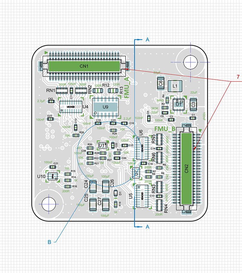
Example Drawing
The following image shows examples of section views, callouts to specific connectors, and general component locations. These are the types of features that are capable in CAD tools and help clarify specifics on your drawing for the contract manufacturer.
With clear CAD drawings, the design is properly documented and helps provide consistency from one run to the next or one contract manufacturer to another.
Although drawings are helpful, it’s always best to run through them with your contract manufacturer and make sure both parties interpret the drawing correctly. This gives you, the designer, the ability to remove ambiguity from your documentation.
Need Help With Your Project?
BuildEmber provides electronics engineering and PCB layout services for all industries. Our team has experience in power electronics, motor drives, mixed-signal, precision analog, and high-speed digital. Our team works with you to create a new design or take your existing design to the next stage of manufacturability, assembly, and reliability for mass production.
Visit us at buildember.com
Call at 832-391-5516 or email at contact@buildember.com
No responses yet