Component library management comes in all shapes and sizes. From simple integrated libraries all the way to full PLM integration with a native design tool, picking a solution that fits your needs requires careful consideration.
If your company is using Altium for its ECAD tool, then you already have a powerful component management tool built into your PCB design software. The one caveat is that the Altium Pro subscription is where the powerful component library management features come into play.
This post focuses on some of the useful features in Altium 365’s component library manager.
Why Do You Need Component Management?
Component library management is a useful for creating a centralized source of truth, preventing recreation of components, and managing a component’s lifecycle. When creating a component with a tool such as Altium 365, you have control over your design, such as:
- Required parameters on a component type basis
- Driving consistent mechanical layer usage across components
- Revision control
- Component lifecycle control
- A single source of truth
Controlling Component Parameters
When creating components in Altium 365, you can dictate required parameters associated with different types of components. For example:
- Resistors – value, tolerance, temperature coefficient, power rating, etc.
- Capacitors – value, tolerance, dielectric material, voltage rating, etc.
- MOSFETs – voltage, current, power dissipation, max junction temperature, etc.
Note: to create a component template and use the features below, you must have the pro version of Altium.
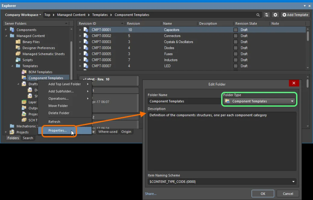
The following image shows Altium 365’s Explorer window where you can create a container folder for component templates

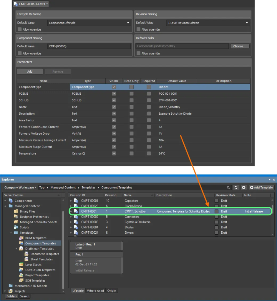
After creating a component template folder, you can use the component template editor to create parameter types and set if they are required to fill out prior to an initial release of the component.

Dictating parameters is important for consistency across schematics, displaying key parameters on schematic symbols, and a single source for exporting all component information.
Consistent Component Mechanical Layer Usage
Altium doesn’t specify whether certain mechanical layer numbers are reserved for a specific function, so it’s possible to have inconsistencies between components in you layouts.
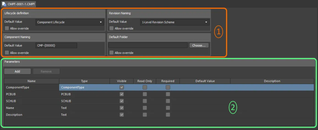
Using the component template editor, you can define a default PCBLIB and SCHLIB to your component type (box number 2). Using this editor, setting a default PCBLIB allows the library manager to give a starting point for the footprint. You can use this PCBLIB to set up the default mechanical layers and their layer numbers which will drive consistency in your library components.

The same is true with the SCHLIB which allows for definition of a default component schematic symbol. For example, if this component template was for a resistor, you could assign a default resistor symbol to ensure consistent schematic symbols across your designs.
As part of a SCHLIB default, you could specify which parameters you want to display on a component. On a capacitor for example, you may want to have voltage, package size, dielectric, and tolerance in addition to the value.
Notice this also attaches a lifecycle definition to the component.
Revision Control
Altium 365 natively uses Git under the hood for version control. Any time a change is saved to your Altium 365 instance, there is a paper trail. This allows complete visibility for what was changed during each iteration of an Altium 365 object. This is helpful in the event you need to revert to a previous version or have visibility into how managed objects are updated.
The following image is an example of selecting two schematic revisions and comparing them.

Altium allows for comparison of object differences like so:

Component Lifecycle Definition
Why is it important to dictate the lifecycle of a component?
Imagine you’ve created a component for a design. Some component footprints and schematic symbols can be complicated. Ideally, one person would create a component and another designer would review the component. With lifecycle definitions, you can tag components to clearly track an initial release of a component followed by a change of state after reviewing the component. This gives confidence prior to fabrication that you won’t have an incorrect pin mapping or footprint definition.

To continue this scenario, you can then move to a production state when the fab has been built and tested to be correct. If issues come back during DFM or DFT, you can correct these issues and address them prior to moving your component to a stage like production.
Summary
If you’re currently using Altium and have a need for component library management, Altium 365 has many features that traditionally have been implemented separately and integrated in to the tool.
As part of the PCB design software, now it’s all included and is extremely feature-rich. You can drive consistency in your components while creating some gating requirements for different component types. You also have the ability to drive component lifecycle management with revision control.

Need help with electronics design and software development? Reach out to BuildEmber for a consultation at contact@buildember.com or 832-391-5516.


No responses yet